
Understanding Three-Conductor Cable Fundamentals
Defining the Three-Wire Configuration
It’s a well known secret that electricians rarely agree on anything, except perhaps the universal annoyance of untangling a stiff 3 core electrical cable on a cold morning. This is the workhorse of residential and light commercial installations. Instead of juggling multiple single conductors, this configuration bundles everything into one neat, robust sheath.
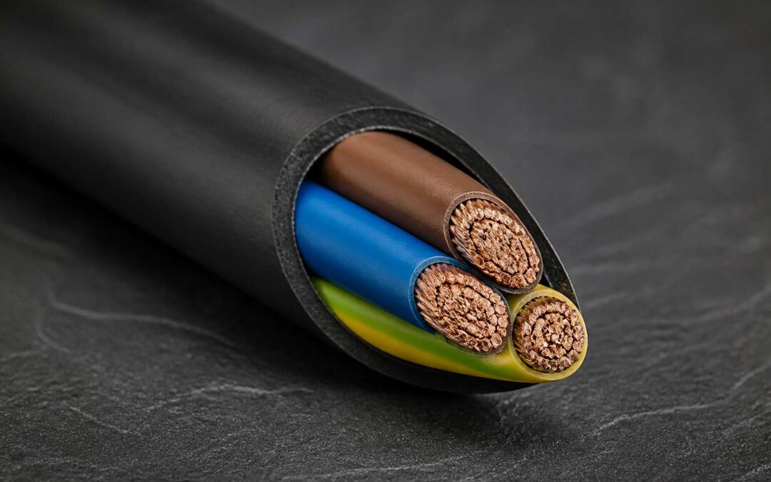
To truly grasp its utility, one must break the cable down to its basic anatomy. Each wire performs a specific, non negotiable duty:
– The brown insulated conductor serves as the live feed, carrying current to the appliance.
– The blue conductor returns this current safely to the distribution board.
– The bare or green and yellow striped copper acts as the circuit protective conductor, the very element that prevents fatal shocks during a fault.
The sheer practicality of this design is stunning. In South Africa, you will often find this cable specified for wiring up geysers, stoves, and even garden lighting. It is the classic choice when a double pole switch is required to isolate both live and neutral lines. This arrangement keeps your wiring tidy, reduces installation time, and ensures compliance with local wiring regulations.
However, the specific colours and standards have evolved over the years. Older installations might surprise you with a red live wire and a black neutral. If you are renovating a property with vintage wiring, you must verify the termination points with a proper voltage tester. Safety protocols do not change with age, only the habit of the wire colours do. Understanding this cable type ultimately prevents you from creating a spaghetti mess of wires in a junction box. It is a system designed for logic, clarity, and absolute safety. Quite the trio!
Typical Applications Across Residential and Industrial Settings
It is easy to overlook the silent workhorse behind every flick of a switch, yet the humble 3 core electrical cable underpins the rhythm of modern life. We often admire the finished ceiling light or the instant heat from a kettle, but the true engineering marvel lies within the conduit, hidden behind plaster and trunking. This conductor trio is not merely a product; it is a system of structured energy flow that governs how we interact with power every single day. The flexibility of this design allows it to snake through roof trusses in Johannesburg and industrial plants in Durban with equal ease.
The true measure of this cable is its chameleon-like adaptability across vastly different environments. In the residential sphere, it governs the heavy lifting of daily domesticity, from powering robust stoves to managing the significant load of a standard geyser. The industrial application, however, tests its mettle in far harsher conditions. Here, the cable must endure constant vibration and potential chemical exposure while maintaining a flawless performance record. It bridges the gap between the raw power of the grid and the finesse required by sensitive control panels.
When you look at the specific settings where this cable thrives, a clear pattern emerges regarding its installation:
– Wiring for double pole switches that necessitate a complete disconnection of the supply.
– Fixed equipment installations where the load is too great for standard flexible cords.
– Sub-main circuits feeding distribution boards in multi-story buildings.
– Outdoor lighting columns where the protective conductor is essential for structural safety.
It is in these varied terrains that the practicality of the design becomes apparent. The consolidation of the live, neutral, and earth into a single sheathed entity reduces the risk of accidental disconnection during routine maintenance. It forces a discipline on the installer that separate wires often lack. By centralising the core functions, we create a safer, more logical grid that can be traced and tested with greater accuracy. This is the foundation upon which reliable electrical infrastructure is built, ensuring that our reliance on power remains an unspoken convenience rather than a noticeable concern.
Comparing with Two-Conductor and Four-Conductor Alternatives
Electrical circuits are a study in balance, and the 3 core electrical cable represents a specific architectural choice. This configuration creates a self-contained system for the live, neutral, and earth conductors. In my experience, the distinction between this and a two conductor variant often comes down to the presence of that third protective element. Without it, the installation relies on the metallic structure of the building or appliance for fault protection, a practice that is now largely obsolete in new South African builds.
The comparison becomes more complex when we consider four conductor cables. A 3 core electrical cable typically serves a single-phase circuit where the earth is integral. The four core alternative, however, often exists for three-phase systems, carrying three live phases and a neutral, or as a two-way switched live arrangement. The selection is not about one being superior, but about matching the conductor count to the specific functional requirement of the load. Here is how the logic generally breaks down:
1. Two core for simple, double-insulated appliances where earth protection is not required.
2. Three core for circuits requiring a protective earth, such as metal light fittings or standard wall sockets.
3. Four core for complex interlinking or three-phase distribution where load balancing is critical.
When you are planning a fixed installation, the decision between a 3 core electrical cable and its counterparts is dictated by the wiring regulations and the necessity of the earth path. Choosing a two core cable for a metal body appliance is a dangerous compromise. Conversely, opting for a four core cable for a residential light circuit introduces unnecessary complexity and cost. The fundamental understanding is that the third core often provides the safety net, while the fourth core provides versatility in switching or phase distribution. For most standard South African domestic and commercial wiring, the 3 core electrical cable remains the most practical, efficient choice for balancing safety and simplicity.
Historical Evolution of Three-Core Cable Design
3 Core Electrical Cable: A Practical Guide for South African Installations
Think of your home’s wiring as its nervous system. Every light, plug, and appliance depends on this network to function safely and efficiently. The 3 core electrical cable often sits at the heart of this system, and its role is more specific than many realise. For the average homeowner or DIY enthusiast, understanding what this cable does is a matter of both practicality and safety.
At its most basic, a 3 core electrical cable contains three individually insulated conductors within a single outer sheath. In South Africa, these are typically colour-coded: red or brown for live, black or blue for neutral, and a green and yellow striped conductor for earth. This three-in-one design is what makes it the go-to choice for a wide range of fixed installations.
The Non-Negotiable Role of Earth
The presence of that third, earthed conductor is the defining feature. In older installations, two-core cables were common, relying on the metal conduit or the appliance’s casing for fault protection. Modern regulations, however, have shifted. The SANS 10142 standard, which governs wiring in South Africa, mandates a dedicated earth conductor for most new circuits.
Why the change? Simply put, a dedicated earth provides a clear, low-resistance path for fault current to travel back to the distribution board. This ensures the circuit breaker trips quickly, preventing electric shock or fire. Without it, a fault could leave dangerous voltages on metal surfaces, turning a simple appliance into a hazard. The 3 core arrangement addresses this directly, creating a safer environment for your family or your business.
Where You Will Find It
If you are planning a new circuit for a geyser, a stove, or a standard wall socket, a 3 core electrical cable is likely what you need. It is the standard choice for connecting these fixed appliances. You will also find it in lighting circuits where switches are used, providing the necessary live, neutral, and earth paths.
Here is a simple breakdown of how the conductors are used:
– Live (Brown or Red): Carries the current from the distribution board to the appliance.
– Neutral (Blue or Black): Carries the current back from the appliance to complete the circuit.
– Earth (Green/Yellow): Provides the protective path for fault current, safeguarding against electric shock.
Beyond the Basics: A Question of Balance
While the three-core cable is a staple, the choice of cable isn’t always straightforward. Take three-phase power, common in industrial settings. These systems require cables with multiple cores for the different phases. A four-core cable, for instance, is often used to carry three phases and a neutral. The decision comes down to the specific requirements of the load and the nature of the supply.
South Africa’s diverse landscape also plays a part. From the humid coastal regions of KwaZulu-Natal to the dry, hot climate of the Northern Cape, environmental factors can influence cable selection. For outdoor or underground runs, you would need a cable with different insulation properties, like a steel wire armoured (SWA) cable, which offers extra mechanical protection. The core principle of having a dedicated earth, however, remains a constant safety priority.
Your Next Step
Dealing with electricity is not a guessing game. While understanding the role of a 3 core electrical cable is a great start, a professional electrician is essential for any significant wiring project. They can verify your installation is compliant with all local regulations. When you need quality cabling for the job, finding a reliable electrical cable supplier is your first point of call to get the project moving in the right direction.
Construction and Material Composition
Conductor Metals: Copper vs. Aluminium
A staggering 80% of electrical failures are traced back to poor connections, not the cable itself. That truth fuels my obsession with what is inside the jacket. The metallurgy of the conductor often dictates how well that connection holds up. In a 3 core electrical cable, copper and aluminium are the primary contenders, each with a specific set of characteristics that affect installation and performance. Copper, with its high tensile strength and lower resistance, is often the default choice for its reliability. Aluminium, however, is a lighter and more affordable alternative, though it requires a larger cross-section to carry the same current.
The thermal expansion rates of these metals also demand attention. Copper is less forgiving with movement, while aluminium’s softness can lead to cold flow and loosening lugs. This is a critical distinction for the specific application of a standard 3 core electrical cable. Here are the key differentiators to consider for installations:
– Copper is heavier, which affects drum length and support.
– Aluminium requires anti-oxidant paste to prevent corrosion.
– Copper is easier to terminate without special washers.
Choosing between them is rarely about intelligence; it is about the specific demands of the load. I prefer copper for its longevity. Yet, I have seen too many installations succeed with aluminium when correctly managed. The final choice always rests on the budget and the environment, not just the price per meter.
Insulation Layers and Their Thermal Properties
For every 10°C rise above the rated temperature, insulation lifespan drops by half. That single fact dictates how South African engineers select a 3 core electrical cable for outdoor or industrial use. The insulation layer, often dismissed as simple wrapping, determines whether a circuit survives the scorching Highveld summers.
Polyvinyl chloride (PVC) remains the default choice for its easy handling and economy. Its continuous service temperature caps at 70°C. Cross-linked polyethylene (XLPE) offers a 90°C ceiling, which matters when cables cluster together in a trunking.
- PVC: low cost, flexible, but susceptible to thermal aging.
- XLPE: higher thermal tolerance, resistant to moisture.
- Ethylene propylene rubber (EPR): excellent for dynamic bending.
In my years inspecting installations, I have learned that matching the insulation’s thermal rating to the load profile matters more than the brand name. A 3 core electrical cable with PVC insulation may be perfectly adequate for a residential geyser, yet utterly unsuitable for a mining conveyor.
Sheathing and Outer Protective Coatings
Armouring and Shielding for Enhanced Durability
A 3 core electrical cable is more than just a trio of conductors wrapped in plastic. Its true resilience comes from the layers of defence built into its construction, specifically the armouring and shielding. These components are the silent guardians that ensure power flows reliably through harsh environments, from industrial plants to underground installations.
The armouring, often a layer of galvanised steel wire or steel tape, provides the primary mechanical protection. This robust layer shields the inner cores from crushing impacts, rodent damage, and the physical stresses of pulling or direct burial. Without this metal jacket, the cable’s integrity would be compromised by the very ground it is laid in. This is a critical feature for installations where the cable cannot be easily inspected or repaired.
Shielding, on the other hand, serves a dual purpose. It protects the cable’s own signal integrity from external electromagnetic interference, and it also contains the magnetic field generated by the current within. This is particularly vital in data-sensitive environments or when running power alongside communication lines. A proper shield ensures the transmitted power remains pure and uninterrupted.
The specific material composition of these layers is just as important as their presence. The choice of steel wire for armouring is dictated by its high tensile strength, while the copper or aluminium tape used for shielding is selected for its excellent conductivity and flexibility. Together, these materials form a formidable barrier that extends the cable’s service life significantly.
Here is a quick breakdown of their key roles:
– Armouring provides mechanical strength and impact resistance.
– Shielding minimises electrical noise and prevents interference.
– The armouring layer also acts as a path for fault current to earth.
– The shield ensures a stable and consistent electrical signal.
By combining these protective elements, a 3 core electrical cable is transformed into a highly durable and reliable conduit. It can withstand the harshest conditions while maintaining impeccable performance. This thoughtful engineering is what makes it a trusted choice for demanding power distribution, ensuring that the lifeblood of your operation continues to flow without interruption.
Colour Coding and Phase Identification Standards
The construction of a 3 core electrical cable is straightforward, yet it hinges on precision. Within a single outer sheath, three individually insulated conductors are laid together. Each conductor serves a distinct purpose, and their insulation layers are colour-coded to prevent errors during installation and maintenance. This system is not merely decorative; it is a fundamental safety language used by electricians across South Africa.
Identifying the function of each core is critical. The colour coding for a standard 3 core electrical cable follows a clear pattern, ensuring consistency across different installations. You will find:
– A brown insulated conductor designated as the live wire, carrying the current from the source.
– A blue insulated conductor serving as the neutral wire, completing the circuit.
– A green and yellow striped conductor acting as the earth wire, providing a safe path for fault currents.
This colour standard is governed by regulations, making it an essential reference for any project. For a professional, recognising these phase identification markings instantly is non-negotiable. The live and neutral cores handle the standard current flow, while the earth core is a crucial safeguard. Its proper connection protects both equipment and personnel from electric shock. This is why the integrity of the insulation and the clarity of the colour coding are so heavily scrutinised on a quality 3 core electrical cable. The entire system works together to make the installation process safer and more efficient, reducing the risk of dangerous misconnections.
Electrical Performance and Rating Specifications
Voltage Ratings and Insulation Classifications
A 3 core electrical cable must meet strict performance criteria to operate safely under varying loads. The voltage rating defines the maximum continuous voltage the insulation can withstand between conductors and earth. For most South African domestic and light commercial installations, a 600/1000V rating is standard, offering a robust safety margin for single-phase systems operating at 230V.
Current carrying capacity is equally critical. This specification depends largely on the conductor cross-sectional area and the installation method. For example, a 2.5mm² cable clipped directly to a surface might carry up to 27 amps, whereas the same cable running through thermal insulation in a wall will have a significantly reduced capacity. This derating factor is a crucial consideration for any electrician or specifier.
Thermal limits also play a pivotal role in the cable’s electrical performance. Insulation materials, such as PVC or cross-linked polyethylene (XLPE), have specific maximum operating temperatures. Exceeding these temperatures can accelerate insulation ageing and lead to premature failure. A typical 3 core electrical cable with PVC insulation is rated for a maximum conductor temperature of 70°C, while XLPE versions can often handle up to 90°C, providing greater headroom for demanding applications. These specifications are the hidden parameters that determine system reliability.
Current Carrying Capacity and Derating Factors
The ampacity on a datasheet tells only part of the story. For a 3 core electrical cable, the published current capacity assumes pristine conditions: clipped to open air, a 30°C ambient, no heat traps. South African installations rarely oblige. A cable buried in dense clay loses more capacity than one in well-drained sand. A group of cables running together retains heat, forcing each conductor to shed load.
Derating factors correct for reality. The installer must apply them before selecting conductor size. These factors vary with installation method, ambient temperature, grouping, and soil thermal resistivity. Take a 6mm² 3 core electrical cable: clipped direct it might carry 47 amps, but routed through an insulated cavity that figure drops to around 36. That’s a significant reduction,and ignoring it risks overheating.
- Ambient temperatures above 30°C demand proportional reductions.
- Multiple cables bunched together require grouping factors.
- Buried runs depend on soil type andmoisture content.
Temperature Tolerances and Operating Conditions
In a country where load shedding remains part of daily life, the resilience of your wiring is not just a technical detail. It is a commitment to safety that endures through every blackout and power surge.
Electrical performance for a 3 core electrical cable involves more than just conductivity. It is about how the cable maintains stability when the grid falters and temperatures fluctuate. The operating conditions dictate the lifespan of the installation, demanding a material that withstands thermal expansion without compromising the integrity of the insulation. Continuous operating temperatures for standard PVC insulated cables generally sit at 70°C for the conductor, while the short-circuit rating can exceed this for a brief, permitted duration.
Environmental tolerances matter just as much as heat. A cable must reject moisture and resist UV degradation. For South African conditions, consider the following operational parameters:
– Maximum conductor temperature: 70°C (normal operation)
– Minimum bending radius: 6 to 8 times the overall diameter depending on the voltage rating and armouring
– Ambient installation temperature: typically between -5°C and 50°C for flexibility without cracking
The relationship between the load current and the conductor’s temperature is decisive. When you ignore these tolerances, the dielectric stress increases, and the insulation ages rapidly. Ultimately, a 3 core electrical cable exists to manage the delicate balance between the heat generated by current flow and the ambient temperature that dissipates it. Ignore the operating standards, and you create a fire hazard hiding inside your wall.
Resistance, Impedance, and Power Loss Considerations
Electrical performance is the silent contract between a cable and the energy it carries. For a 3 core electrical cable, this contract is defined by precise scientific limits rather than vague promises. The primary metric is resistance, which dictates how much energy is lost as heat during transmission. Copper conductors in a standard 3 core electrical cable offer low DC resistance, but this value shifts with ambient temperature and load. An installer must account for this change to prevent voltage drop over long distances, especially in industrial settings where tools demand consistent power.
Voltage drop is the tangible enemy of efficiency. When current flows through a conductor, impedance creates opposition, and the resulting loss manifests as reduced voltage at the load point. For a 3 core electrical cable, impedance is influenced by the spacing between cores and the frequency of the supply. A higher impedance means a higher voltage drop, which leads to dim lights, sluggish motors, and premature equipment failure. Selecting the correct cross-sectional area mitigates this, ensuring the delivered voltage remains within the acceptable 5% tolerance mandated for most installations.
Power loss is the inevitable byproduct of resistance, expressed in watts and converted into heat. This is where the rating of a 3 core electrical cable becomes critical. The conductor must dissipate this thermal energy without exceeding its insulation threshold, typically 70°C for PVC. If the cable is grouped with others or routed through insulated walls, the heat cannot escape, forcing a derating of the cable’s nominal current capacity. Ignoring this factor leads to insulation breakdown, short circuits, and fire hazards.
Understanding these characteristics allows for informed choices:
1. Resistance determines the voltage drop, so calculate the total circuit length before selecting the conductor size.
2. Impedance affects the power quality, so consider the reactance for high-frequency or long-distance runs.
3. Power loss defines the heat generated, so apply correction factors for ambient temperature and installation methods.
A 3 core electrical cable fails not because of poor materials, but because of poor planning. The numbers on the sheath are a starting point, not a guarantee. Matching the conductor size to the actual current draw and the physical environment ensures the circuit operates safely under full load. When the grid stutters or a motor starts with high inrush current, the cable’s electrical performance determines whether the system survives the surge or succumbs to the spike.
Flexibility and Bending Radius in Dynamic Applications
Flexibility often determines whether a 3 core electrical cable survives a dynamic installation. In South African factories and workshops, cables on robotic arms or cable chains face constant movement, so the bending radius becomes a critical specification. A tight radius strains the copper strands and insulation, leading to premature failure.
Manufacturers design flexible variants with finer stranding and special compounds. The minimum bending radius, usually expressed as a multiple of the cable diameter, must be respected during installation. For dynamic applications, the radius should be larger than for static use.
- Check the cable’s flex rating for continuous motion
- Use proper cable carriers to prevent kinking
- Inspect for abrasion where the cable rubs against surfaces
Ignoring these factors turns a reliable 3 core electrical cable into a maintenance headache. Always match the cable construction to the actual movement profile.
Installation Practices and Safety Compliance
Adherence to National and International Wiring Regulations
A staggering proportion of electrical failures trace back to improper handling during installation, not manufacturing defects. The journey of a 3 core electrical cable from the drum to the distribution board determines its lifespan more than any other factor. On a South African worksite, from the windy Cape Flats to the humid KwaZulu-Natal coast, the environment dictates the methodology. Cables must be protected from physical damage, but they also require careful attention to their minimum bending radius. Pulling a 3 core electrical cable around a sharp corner creates internal stresses that lead to premature insulation breakdown, a costly mistake that often remains hidden until years later.
Compliance with national standards is a legal requirement, not a stylistic choice. The SANS 1507 specification governs the performance of these cables locally, but adherence to international benchmarks like IEC 60502 is equally critical for imported equipment. Installers must verify the cable’s sheath material matches the ambient temperature rating. A standard PVC sheath will soften in direct sunlight on a Johannesburg rooftop, whereas a tougher chlorosulfonated polyethylene (CSP) sheath handles the UV exposure with far greater resilience. Matching the conductor size to the specific circuit load is a fundamental safety practice, preventing dangerous thermal buildup.
Regulatory alignment ensures the entire electrical network remains coherent and safe. When connecting a 3 core electrical cable, the earthing conductor must be terminated with absolute integrity. A loose connection in the earth path creates a silent hazard, turning metal enclosures into potential shock points. Regular insulation resistance testing, using a megger, is a proactive measure that reveals degradation before it becomes a threat. For the conscientious electrician, the process involves a clear sequence of checks:
1. Verify the cable’s voltage rating exceeds the circuit’s nominal voltage.
2. Confirm the gland is correctly sized to relieve mechanical strain on the conductors.
3. Ensure the live and neutral conductors are identified at both ends to prevent phase mixing.
The physical security of the installation is as important as the electrical logic. Running a 3 core electrical cable through conduit protects it from rodent damage and accidental impact, but the conduit must be fully sealed against moisture ingress. Water inside the conduit is a known catalyst for corrosion, leading to increased resistance and eventual failure. Training and certification are the final components of this safety matrix. The industry moves forward when every electrician understands that a high-quality 3 core electrical cable is only as reliable as the hands that terminate it. Every clean cut and properly torqued connection is a quiet promise of continued safety.
Proper Termination, Splicing, and Connection Techniques
A loose lug is the quiet saboteur of many electrical systems. Reports from insurance assessors and electrical contractors consistently point to termination points as the primary site of failure, where vibration and thermal cycling slowly undo the work of an installer. The physical act of terminating a 3 core electrical cable demands a level of care that borders on the obsessive. Stripping the sheath requires a blade depth set to the insulation thickness, not the copper underneath. A nicked conductor becomes a hotspot, a place where resistance builds and heat follows.
The sequence of work is non-negotiable. Every connection tells a story of the installer’s discipline, or lack thereof. Wire brushing the conductor before insertion ensures oxidation does not compromise the flow of current. Tightening the gland nut with a torque wrench, not a feel, guarantees the seal holds against moisture. In coastal regions like Durban, where salt air accelerates corrosion, this attention to detail is the difference between a system that lasts and one that fails unexpectedly.
Proper splices require the same reverence for the physical. Twisting conductors together and wrapping them in tape is not a splice. It is a hazard. A proper splice uses a compression connector rated for the conductor diameter and the current load. The assembled 3 core electrical cable must maintain its mechanical strength and insulation integrity, which means every joint is a deliberate assembly of parts, not a quick fix.
To gauge a connection’s viability, the installer must physically inspect and test:
1. The depth of conductor insertion into the terminal block.
2. The absence of stray copper filaments that could bridge phases.
3. The integrity of the stress cone or insulation shield at the termination point.
The craft lies in the preparation of the conductor ends. Clean, square cuts and a precise strip length create a termination that performs under load. A carelessly prepared end on a 3 core electrical cable introduces an impedance mismatch that generates heat and degrades the insulation from the inside. The moment of tightening the screw terminal is a final contract between the electrician and the circuit. There is no room for approximation. The quiet discipline of this work is what separates a robust installation from a latent defect.
Bending, Pulling, and Cable Routing Best Practices
The bending radius of a 3 core electrical cable is a specification, not a suggestion. Pulling a cable around a tight corner to save three metres of tray causes premature insulation failure. The copper inside does not care about your schedule.
A cable gland is not a handle. When routing the cable, use the correct pulling grips and lubricate the conduit. Sharp edges damage the sheath. In South African industrial sites, the difference between a clean installation and a tangled mess is visible within minutes of walking the route.
- Confirm the pulling eye is rated for the cable weight.
- Check the conduit for debris before pulling.
- Verify the bend radius matches the manufacturer’s recommendation.
Vertical runs need proper support at each floor level. Horizontal runs require cleats spaced to prevent sagging. The physical handling of a 3 core electrical cable during installation determines its performance years later.
Common Installation Errors and How to Avoid Them
Statistical reports from the South African Occupational Health and Safety Act indicate that a significant percentage of electrical failures originate from installation phase oversights. When a 3 core electrical cable arrives on site, the battle for its longevity is already underway. The most insidious errors are not the dramatic ones, they are the subtle deviations from the manufacturer’s data sheet. Technicians often interpret torque specifications as suggestions, leading to loose connections that generate heat under load.
Inspection of past failures reveals a pattern of mismatched components. A 3 core electrical cable terminated with undersized lugs creates a high resistance junction. This is a primary source of cable failure in industrial plants.
Common compliance failures include:
– Improper segregation from data and communication cables.
– Using a cable type not rated for the ambient soil temperature.
– Neglecting to install a separate earth continuity conductor where required.
– Failing to torque glands to the specified values for the specific cable armor.
The verification of circuit integrity after installation is often rushed. It requires a methodical approach. The subtle difference in thermal expansion between copper conductors and aluminium lugs is a known problem. The electrician who walks away from a job without testing the insulation resistance of the 3 core electrical cable has only completed the visual part of the work. The process of certification should be as rigorous as the physical installation, leaving nothing to the vague hope that the cable will simply work.
Testing and Verification Procedures Before Energizing
The moment before energizing a new circuit is a gamble, even with the finest 3 core electrical cable on the market. You have pulled the conductors, dressed the glands, and terminated the lugs. But visual perfection is a liar. The real test begins when voltage hits the copper.
Insulation resistance testing is your first line of defense. A megger reading below the benchmark of 100 megaohms for a new installation is a red flag. It indicates moisture ingress or a nicked jacket that occurred during the pull. Do not overlook conductor continuity either. A loose connection hidden inside a junction box will not show itself until the load is applied, which is precisely when the heat builds and the insulation degrades.
Here is a practical sequence to verify your work before you flip the main breaker:
1. Perform a thorough visual inspection, checking for mechanical damage to the sheath.
2. Conduct an insulation resistance test between all phases and earth.
3. Verify conductor polarity and phase sequencing.
4. Test the integrity of the earth continuity path.
Beyond the electrical checks, consider the physical environment. Is the 3 core electrical cable secured with the correct derating factor for the ambient temperature? A cable running through a roof cavity in Durban in summer faces different thermal conditions than one in a conduit in Johannesburg. If you have not adjusted the protective device rating to match this derating, the cable will operate hotter than its designated rating, shortening its lifespan.
Compliance is a documentation exercise as much as a technical one. The certificate of compliance (COC) is a legal declaration, and vague notes about “tested and found OK” are worthless. Record the actual measured values. If the earth fault loop impedance is high, trace the issue back to the cable installation method, not the terminations. The correct installation of a 3 core electrical cable is a combination of physics, patience, and following the wiring regulations to the letter. Skip the verification process, and you will likely meet this cable again under less pleasant circumstances, involving a tripped breaker and a burning smell.
Selection Criteria and Procurement Considerations
Assessing Load Requirements and Cable Sizing
Selecting the right 3 core electrical cable begins with a precise assessment of the load it must serve. Calculate the steady state current, but also account for starting surges and any future additions to the circuit. Undersizing leads to overheating and premature insulation failure, while oversizing wastes capital for no operational benefit.
Voltage drop over long runs deserves equal attention. A cable that carries current adequately at the origin may still deliver insufficient voltage at the load point, especially in industrial yards or rural installations. Use the allowable percentage drop from SANS 10142 to guide your conductor cross section.
- Confirm the ambient temperature profile along the entire route
- Check whether the cable will be grouped with others, which reduces ampacity
- Verify the fault level and protection device coordination
Procurement should focus on certified suppliers who provide batch test certificates and traceable raw materials. A cheaper 3 core electrical cable without SABS approval often hides substandard copper or thin insulation, creating long term liability. Balance upfront price against verified performance and warranty terms.
Voltage Drop Calculations for Long Cable Runs
Procurement looks like a formality until a drum arrives with conductor diameters that fall below the stated spec. I have been on site where a 3 core electrical cable carried the SABS mark yet measured 0.3 mm thin on the copper. That gap multiplies resistance and heats the insulation from the inside. Take a micrometer, strip the outer sheath, and measure the actual strand before you sign.
Voltage drop, on the other hand, is a calculation too many people do once, when they should rerun it for the precise route or conduit temperature. The correct method uses the conductor’s practical resistance at that operating heat, then the addition of the outward and return paths.
For each long cable run, I have a short checklist:
- Measure the resistance of the actual drum, not the catalogues figure.
- Rerun the voltage drop at 70 degrees Celsius, not at 20.
- Confirm the protective device trips before the cable is damaged.
That routine saves a 3 core electrical cable from failing under an innocent load.
Environmental Factors: Moisture, UV, and Chemical Exposure
Sun in the Karoo degrades PVC faster than any classroom chart suggests. Coastal air carries salt that creeps into terminations. When I procure a 3 core electrical cable for outdoor exposure, I read the datasheet for hydrolysis resistance, not just tensile strength. The sheath is the first barrier against premature failure.
- Moisture ingress through damaged sheaths
- UV stabilisers that slow embrittlement
- Chemical vapours from industrial processes
Each factor changes the polymer compound. A cable that lasts years in Johannesburg might fail in Durban’s humidity. The procurement conversation is really about matching the jacket to the environment, not the copper rating. I have seen perfect conductors rot from the outside because no one asked about the soil pH. That oversight turns a simple purchase into a replacement cycle.
Cost Analysis: Initial Investment vs. Long-Term Durability
Selection Criteria and Procurement Considerations
The moment of selection follows a quiet logic of its own. When I hold a 3 core electrical cable in my hand, I am not holding a single object but a contract between material and place. The quiet mathematics of lifetime cost rarely appears on a quotation. Those numbers arrive later, in the field, when a cheap cable rusts through its second year or a middle ground option carries the system for decades.
The purchase price is a wound, and the healing happens over time. A business owner recently told me that replacing the same section of cabling three times in five years cost more than the entire electrical installation of their new facility. I have learned to listen to such stories.
Think of the cost breakdown like this:
– Initial capital outlay for the 3 core electrical cable itself
– Installation labour, which rises with less flexible sheath types
– Downtime expenses during any replacement cycle
– The price of a single failed inspection
The real ledger balances more than just rands and cents. A professional can see it in the first formula: operating lifespan divided by upfront cost. The true metric is the same as in any long term relationship: how well it ages.
Certification, Brand Reliability, and Supplier Vetting
Procuring a 3 core electrical cable demands more scrutiny than a glance at the price tag. Selection criteria must align with SANS 1507 standards, ensuring the conductor size and insulation ratings match the specific load profile. Without this, compliance is a risk.
- Verify the certificate of compliance matches the batch number.
- Inspect the conductor material for copper purity.
- Confirm the sheath thickness against the stated specifications.
Supplier vetting is equally vital. A reliable supplier maintains traceable stock. Brand reliability in the South African market is established through years of consistent performance in harsh conditions. I have seen installations fail simply because the initial procurement prioritised margin over measurement. Always check the technical data sheet against the delivered 3 core electrical cable. The paperwork is the real safeguard.