
Understanding Cable Fault Fundamentals
What Are Cable Faults and Why Do They Occur?
Nearly 40% of electricity distribution losses in South Africa stem from hidden cable faults. A cable fault is any physical or electrical failure that disrupts current flow. These failures stay underground, making systematic detection essential.
Faults are not random events. Thermal cycling weakens insulation over years. Water seeps into joints and corrodes metal. Ground movement from construction stretches cables beyond limits. Each cause leaves a distinct signature.
- Insulation breakdown due to overheating
- Moisture penetration in underground ducts
- Impact damage from excavation equipment
When a fault occurs, an electrical cable fault locator is the only practical way to find it quickly. In my experience, a good locator pins down the fault in minutes, not hours of trial digging. That speed matters! Without such a tool, repair crews face blind digging and prolonged outages. The electrical cable fault locator reduces downtime for utilities and industrial plants.
Primary Types of Cable Faults: Open, Short, High Resistance, Low Resistance
Every cable fault falls into one of four categories. Open circuits sever the conductor completely, halting current with a clean break. Short circuits arise when failed insulation lets conductors touch, producing a low impedance disaster. High resistance faults are the tricksters; they leave partial continuity, but current fights its way through damaged material. Low resistance faults sit close to a short, yet retain some measurable opposition to flow.
- Open: zero continuity.
- Short: direct conductive contact.
- High resistance: degraded path, limited current.
- Low resistance: near short with slight impedance.
An electrical cable fault locator interprets these electrical fingerprints. It separates a high resistance glitch from a total open. That distinction saves time. For a South African crew staring at a dead feeder, knowing which type lurks underground changes the entire repair strategy. The electrical cable fault locator does not dig, but it tells you precisely where to dig.
How Cable Fault Locators Detect and Analyze Fault Signatures
A cable fault is a private event. It happens out of sight, deep within the ground. Technicians experience only the consequence: a darkened factory, a stalled pump, a silent meter. An electrical cable fault locator turns that hidden disruption into a measurable coordinate.
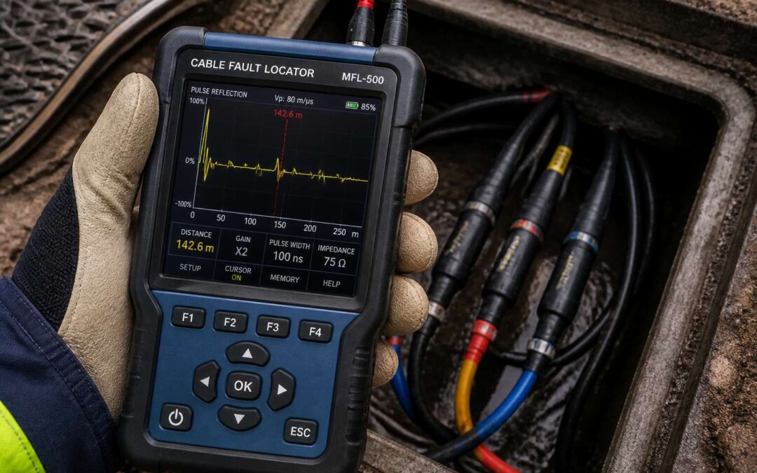
That coordinate comes from a reflected pulse. The locator sends energy down the conductor. When it reaches a break, a short, or a damaged segment, some of that energy returns. The round trip time measures distance. More telling, in my experience, is the shape of the reflection; it describes the fault’s character.
Three factors shape every reflection:
- Impedance mismatch at the fault, which sets the reflection amplitude.
- Fault sharpness, which alters the pulse width.
- Leakage resistance, which attenuates the return signal.
Key Selection Criteria for Cable Fault Locating Equipment
Measurement Range and Accuracy: Matching the Tool to Your Network
The distance to a fault is rarely as precise as field engineers hope. On South African networks, where cable paths twist through mine properties and suburban verges, a ranging error of five percent can mean digging the wrong trench. The measurement range of an electrical cable fault locator decides whether one instrument covers a distribution feeder or merely a segment of it.
Accuracy depends on factors often overlooked in the datasheet. Velocity of propagation drifts with insulation age and soil temperature. In our experience, close-in fault resolution is where many instruments perform poorly. Integrating these parameters into the calculation separates relevant results from misleading echoes. The practical differences appear in:
- Dead zone length, the near-end blind spot that hides close faults
- Output pulse energy, which determines how far the signal can reach
- Signal processing depth, which distinguishes arc reflections from ambient noise
Battery life and weather sealing shape field usability during the Highveld’s thunderstorm season!
Fault Locating Methods: Time Domain Reflectometry, Arc Reflection, and Decay
Selecting an electrical cable fault locator is a decision about method as much as measurement. The instrument’s core technology determines how it interprets reflected signals, and each approach exposes different truths about the fault.
Time domain reflectometry sends a pulse and reads the echo. Arc reflection adds a high voltage kick to ionize the fault path, while decay methods observe the natural dissipation of energy. These are not interchangeable. They suit different fault signatures and network conditions.
Consider these factors when matching the method to your environment:
– Does the unit support multiple reflection techniques without recalibration?
– Can it handle high resistance faults without burning the cable?
– Are the waveforms interpretable on a screen visible in direct sunlight?
The quiet moments before a fault locator fires are where expertise matters. The machine is only as honest as the operator’s understanding of its limitations.
Portability, Ruggedness, and Field Ergonomics
A heavy electrical cable fault locator becomes a liability by midday. Field crews in South Africa traverse rocky terrain, climb into trenches, and work in heat that makes screens glitch. Portability means it fits through a manhole opening. Ruggedness means surviving a drop from a bakkie tailgate.
Look beyond the casing. A sealed keypad resists dust. A bright display with adjustable contrast works under direct sun. Battery life matters more than raw speed when you are hours from power.
Ergonomics determines whether one person manages the test alone. Consider these checks before purchase:
- Can you read the waveform with the unit on the ground?
- Does the lead set stay flexible in cold weather?
- Is the panel navigable with thick gloves?
The physical design of your electrical cable fault locator shapes every field session. A robust carrying harness and strain relieved connectors prevent early failure. Choose equipment that matches your working reality, not the brochure.
Data Connectivity, Software Integration, and Reporting Features
A modern electrical cable fault locator does more than pinpoint a break. It connects to your workflow. Data connectivity transforms a field test into a shared decision. Bluetooth and USB ports let you transfer waveforms instantly. Software integration maps fault data onto cable records. This matters when you manage a sprawling network across Johannesburg or Cape Town.
Consider reporting features. Some units generate PDF reports on site. Others export CSV files for GIS analysis. The best tools let you name files with cable IDs and dates. No more rewriting notes in a bakkie. Ask for a unit that supports firmware updates. That extends its lifespan.
Key criteria to check before purchase:
1. Export formats: PDF, CSV, or both?
2. Mobile app compatibility for live viewing.
3. GPS tagging of fault locations.
4. Cloud backup for field records.
These features reduce admin time. They turn raw data into intelligence. Choose an electrical cable fault locator that speaks your data language.
Battery Life, Charging Options, and Safety Ratings
A field crew knows the real cost of a dead battery. It is the walk back to the truck, the lost afternoon. Battery life determines how many faults you clear before the unit needs a charge. For an electrical cable fault locator, look for runtime that covers a full shift with margin to spare. Some units offer hot swappable batteries, a genuine advantage when far from a plug point.
Charging options matter. In South Africa, load shedding makes a mains only unit a liability. Seek one that accepts 12 V DC from a vehicle. Verify the charging time. An eight hour recharge is a problem when you have multiple faults to chase.
Safety ratings are non negotiable. The equipment works around high voltage and damp conditions. An electrical cable fault locator should meet an ingress protection rating such as IP54 or better. Check the overvoltage category and certification.
Step-by-Step Operational Workflow for Pinpointing Faults
Pre-Test Safety Preparations and Circuit Isolation
Before the locator delivers a whisper of insight, the circuit must be rendered deaf and dumb. A live conductor is a liar, and a grounded cable will skew your trace. You can’t afford a phantom reflection.
- Disconnect the supply and lock out the breaker. Verify the absence of voltage with a calibrated contact multimeter.
- Isolate both the near and far ends. A dead cable connected to a motor or transformer can generate its own interference.
- Ensure the sheath is dry and free of condensation. Surface moisture creates a parallel path that bleeds the test pulse.
Only then can you apply the test signal. In municipal networks around Johannesburg, piecemeal isolation often hides the true fault signature behind a maze of borrowed neutrals. If you skip these steps, you are reading noise, not ohms. An electrical cable fault locator demands this obedience.
Performing Pre-Location to Narrow the Search Area
Pre-location is where the real detective work begins. A raw TDR trace gives you a distance, but that number means little until you convert it to a physical location on the ground. Start by measuring the exact length of the cable from the test point. Divide the TDR reading by the velocity of propagation, and you have a working metres-to-fault estimate.
Now take that distance and pace it out along the route. Mark the spot with chalk. Walk past it by a few metres in each direction. The fault signature will often shift as you approach, and your electrical cable fault locator will show a stronger null or a sharper reflection when you are directly overhead. This is the moment where patience pays off.
- Mark the cable route before testing.
- Walk the estimated distance and note any joints.
- Switch to a receiver for the final few metres.
This narrows the search area from kilometres to metres. A good pre-location pass means you are no longer guessing with a spade. You are walking straight to the fault with an electrical cable fault locator that has already done the heavy lifting.
Applying High-Voltage Surge Testing to Isolate the Fault Zone
High-voltage surge testing isolates the fault zone with a controlled arc. The electrical cable fault locator sends a high-voltage pulse down the cable; the fault gap breaks down and produces a telltale thump. The process follows a strict order:
1. Confirm the cable is isolated and earthed.
2. Connect the surge generator and set the energy level.
3. Apply the pulse and listen for the thump.
4. Move the receiver along the route to find the loudest point.
The time between the surge and the reflected wave gives the distance. The acoustic signal narrows it further. The electrical cable fault locator works where a TDR fails, on high-resistance faults that need voltage to arc. Walk the route slowly, because the thump changes in pitch and volume as you cross the fault. This method homes in on the exact spot, even under concrete or dense soil.
Advanced Location Techniques for Complex Cable Networks
Using Surge Generators and Thumpers for High-Energy Faults
For complex cable networks, a basic electrical cable fault locator often falls short. Surge generators and thumpers deliver high-energy pulses that force a breakdown across the fault, turning a high-resistance issue into a measurable event. This works well in ring or branch networks where reflections get messy.
The key is to combine thumping with voltage waveform analysis. You listen for the thump, but you also monitor the voltage collapse! A sudden drop indicates the exact moment of breakdown.
Consider these steps for high-energy faults:
1. Isolate the branch to reduce reflections.
2. Apply a low repetition rate to let the fault reset.
3. Use the decay method to differentiate cable joints from the actual fault.
Each surge stresses the insulation, so allow cool-down periods. That extra care keeps the electrical cable fault locator readings consistent and your crew safe.
Acoustic and Magnetic Pre-Location Methods for Buried Cables
For every kilometre of buried cable, a hidden world exists beneath the soil, and locating a fault within it often feels like a quiet form of archaeology. The acoustic method listens for the percussion of the discharge. When the surge hits the fault, the earth transmits a dull, distinct crack, a sound that betrays the exact point of damage.
The magnetic method offers a different kind of discernment. It detects the electromagnetic field radiating from the fault during the pulse, a signal that is often sharper than the sound itself. This technique proves particularly useful in noisy environments where ambient sounds drown out the thump.
To streamline the search process, engineers combine both signals.
1. Walk the cable route with a ground microphone to pick up acoustic waves.
2. Use an A-frame receiver to trace the magnetic field gradient.
3. Mark the precise spot where both signals peak simultaneously.
These pre-location techniques guide the operator to a narrow digging zone, saving time and effort. By mastering these subtleties, you turn the subsurface from a mystery into a map, ensuring the electrical cable fault locator is used for final confirmation rather than the primary hunt.
Fault Location in Different Cable Types: Paper-Insulated, XLPE, and Mixed Runs
Modern distribution networks rarely follow simple, uniform paths. They splice together different cable vintages and insulation families. This raises the complexity of any fault location task. An electrical cable fault locator must therefore interpret signatures across diverse construction types. Paper-insulated lead covered cables, historically common in older city centres, behave differently under fault conditions compared to modern cross-linked polyethylene cables.
For instance, paper cable faults present erratic impedance values. The dielectric absorbs moisture, causing variable dissipation factors. This confuses basic time domain reflectometry readings. XLPE, by contrast, exhibits cleaner reflections, but the insulation suffers from electrochemical treeing phenomena. These micro-channels create incipient faults that test the sensitivity limits of the equipment. A skilled operator knows that the locator’s pulse width must be adapted to the specific dielectric character in play.
Mixed runs create another headache, specifically where the impedance changes abruptly.
– Each joint represents a partial reflection event.
– This can mask the true fault signature if the operator is not critical of the trace.
– Comparing the reflection pattern against a known healthy phase is essential.
Navigating these hybrid corridors requires patience. The most effective approach involves using the electrical cable fault locator’s waveform comparison feature to identify the anomaly. Once the suspect section is narrowed, a high-voltage surge pinpoints the physical location. The goal is to match the testing mode with the cable’s age and material logic, allowing you to see through the noise of the joints and insulation quirks.
Remote Monitoring and Telemetry for Fault Location
Remote monitoring is transforming how South African utilities approach cable faults. A single electrical cable fault locator can now interface with telemetry systems that stream waveform data directly to control rooms. This allows engineers to observe partial discharge trends before they evolve into full failures. For complex networks, this changes the game. Instead of dispatching a crew for every suspected issue, operators receive alerts when insulation parameters drift outside expected windows.
Consider the practical benefits:
– Real time impedance tracking across mixed cable sections
– Automatic correlation of fault events with grid loading data
– Remote adjustment of pulse widths and surge voltages
Telemetry adds a layer of foresight. By layering historical traces over live readings, an electrical cable fault locator becomes a diagnostic hub. It no longer merely pinpoints a failure; it helps predict where the next one is likely to form. That shifts the focus from reactive repairs to proactive maintenance, a crucial step for aging infrastructure in South Africa’s growing urban and industrial centers.
Common Challenges, Troubleshooting, and Maintenance Tips
Avoiding Misinterpretation of Reflected Waveforms
Reflected waveforms often mislead because a single trace rarely provides complete information. Ground faults, moisture, and branch joints create echoes that resemble real damage. When using an electrical cable fault locator in South African networks, you must distinguish between a legitimate fault signature and a harmless discontinuity.
Start troubleshooting by verifying the pulse velocity setting. A wrong value shifts every reflection on the axis. Then compare the waveform with a known healthy cable of the same type. Common mistakes arise from ignoring the effect of cable taps or parallel branches.
- Measure the cable length precisely.
- Check for loose shield connections.
- Use a low voltage first to confirm the baseline.
Regular maintenance prevents false readings. Clean the connector of your electrical cable fault locator after each field session, and store the unit with the battery charged above fifty percent. These practices keep reflections sharp and reduce guesswork.
Overcoming Noise, Grounding Issues, and Cross-Coupling Interference
Every live cable radiates electrical noise. In South African industrial plants, variable speed drives and earth leakage currents saturate the environment with interference. That noise reaches your electrical cable fault locator and distorts the reflected waveform into something unrecognisable. Grounding issues compound the problem. A corroded earth stake or a floating shield creates phantom reflections that mimic genuine faults. Cross-coupling interference adds another layer, where adjacent cables bleed energy into the test circuit and produce signatures resembling hard damage.
Work through the noise systematically:
1. Establish a single-point ground.
2. Disconnect parallel feeders where safe.
3. Move the injection point away from known interference sources.
Troubleshooting demands patience. Change the ground position. Adjust the pulse width. Observe how the trace responds to each variable. The electrical cable fault locator does not invent noise. It reports what the network feeds it. Mastering that distinction is the difference between a confident repair and a wasted dig.
Safety Considerations When Working with High-Voltage Equipment
The electrical cable fault locator demands respect for what it can do. Common challenges emerge when harmonic distortion or partial discharge in aged insulation mimics genuine damage. Troubleshooting calls for methodical patience. Inspect test leads for micro-cracks, verify battery integrity, and compare waveform stability across consecutive pulses.
Maintenance ensures accuracy. Clean connectors with approved solvent, calibrate the instrument annually, and house it in a sealed, moisture-proof case. Safety considerations are absolute:
- Isolate the circuit and verify zero energy before connecting test leads.
- Wear rated insulating gloves, a face shield, and arc-resistant clothing.
- Discharge cable capacitance fully before touching any termination.
Never bypass interlocks. Treat every cable as live until proven dead. This instrument reports only what the network feeds it; your vigilance determines the outcome.