
Evaluating the Extent of the Damage
Recognizing Common Types of Cable Wear and Tear
Old cable can be deceptive. Before attempting any repair, surge protectors and voltage testers are set aside until you visually inspect every centimetre. I have found frayed sheathing and corroded copper in unexpected spots. Evaluating the extent of the damage requires a systematic approach: look for discolouration, brittle insulation, or burn marks.
Common types of wear include abrasion from dragging, cracking from ultraviolet exposure, and rodent bites. A quick checklist of warning signs includes:
- exposed wires
- stiff or cracked insulation
- charred spots
Only after this assessment can you consider repairing damaged electrical cable safely. Water intrusion and heat fatigue change all rules.
Using Multimeters and Voltage Testers for Diagnosis
Voltage testers and multimeters should never be rushed. A continuity sweep on a damaged run of wire often produces a drifting reading, which means a loose connection under the sheathing. I trust a multimeter’s resistance scale over any visual clue. It reveals the quiet fault of a conductor that looks perfect on the outside.
For live circuits, a two-pole voltage tester measures the actual potential at the repair point. That number shows whether the break sits on the supply side or the load side. Odd readings, such as a slow decay after disconnection, point to capacitance from water-soaked insulation! That condition changes everything about repairing damaged electrical cable.
Determining Whether to Repair or Replace the Cable
Roughly 40% of cable failures in South African homes hide internal fractures beneath intact sheathing. That statistic shapes every decision about repairing damaged electrical cable. I measure damage in both directions from the visible fault, since oxidation travels further than you might think.
Once the extent is mapped, the repair versus replacement decision depends on three factors: length of damage, cable location, and insulation condition. For exposed runs under three meters, splicing works. For buried or wall-embedded cables, replacement is the only sound choice.
- Repair when the damaged portion is short and accessible.
- Replace when water has reached the conductor.
Essential Safety Measures Before Starting Repair Work
Disconnecting Power and Applying Lockout/Tagout Procedures
Most DIYers ignore the one step that saves lives: cutting power completely. For repairing damaged electrical cable, you must first isolate the circuit at the breaker panel, then verify zero voltage with a tester. But switching off a breaker is not enough. A coworker or family member could flip it back on mid-task.
That is why lockout/tagout procedures exist. They physically secure the switch and warn others. You will need a padlock, a hasp, and a durable tag. Place them correctly, and the circuit stays dead until you remove them.
- Switch the main breaker to OFF.
- Apply the lockout device over the handle.
- Attach a tag with your name and date.
- Test with a multimeter before touching wires.
Taking this extra minute prevents electrocution and arc flashes. Respect the power behind your walls. It demands caution before you begin any repair.
Selecting and Wearing Appropriate Personal Protective Gear
The moment you commit to repairing damaged electrical cable, your skin and eyes become the only barrier between you and stored energy. Personal protective equipment is not a formality. It is a ritual that separates careful work from reckless hope. Even with a verified dead circuit, hidden capacitance can bite without warning.
For this task, your gear must be rated and intact, not merely present. A scratched face shield or cracked glove offers false confidence.
- Insulated voltage-rated gloves with leather over-gloves
- Safety glasses with side shields or a full face shield
- Flame-resistant long-sleeve clothing and cotton underlayers
- Class E safety boots with electrical hazard protection
Wear each piece before you touch a single conductor. The discipline feels heavy in summer, but it keeps you upright when a hidden charge surprises you.
Verifying the Absence of Live Current with Testing Tools
Electricity does not care about your plans. That is the first lesson of repairing damaged electrical cable. You can flip the breaker, hang the lock, and still find 230 volts waiting for you.
Verifying the absence of live current requires your full attention. Your multimeter is the only instrument that tells the truth. Use it correctly, every time.
Before touching any conductor:
- Test your tester on a known live source. If it does not scream, it is lying!
- Test the conductors you plan to work on. Both wires. All terminals.
- Test your tester again on the known live source.
A tester that fails silently is worse than none. I have seen it happen. In South Africa, load shedding leaves circuits in odd states, and a generator or inverter can backfeed a dead cable with enthusiasm.
Setting Up a Dry, Well-Lit Work Area
Moisture compromises everything about a repair. Before repairing damaged electrical cable, test the work surface for dampness with your bare hand. Condensation on walls, a wet patch on the concrete floor, even a humid breeze from an open window can create a conductive path where you least expect it. Dry the area with a cloth or fan, and wait until every trace of moisture evaporates.
Adequate lighting prevents sloppy mistakes. Shadows hide the exact damage you are trying to assess. Place a portable work light on a stable stand, angle it to eliminate glare, and use a headlamp for tight corners. Your eyes need to see every strand of copper clearly.
- Remove all clutter from the immediate floor space.
- Position a fire extinguisher within two metres of your position.
- Keep the work area free of solvents and cleaning agents.
With a dry, well-lit zone, you can focus entirely on the cable in front of you.
Step-by-Step Cable Repair Methods
Cutting Away Frayed or Burned Sections Cleanly
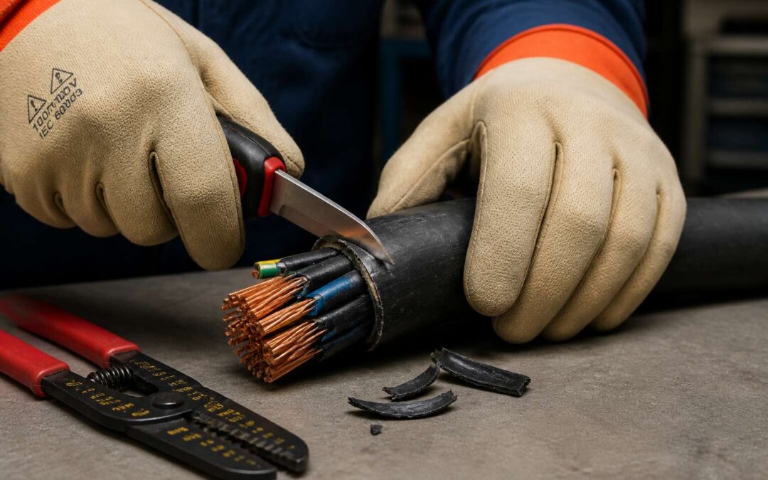
Nothing ruins a repair session faster than a ragged edge. When you are repairing damaged electrical cable, the first cut matters more than the last crimp. Grab a sharp knife or cable cutters, and score the insulation before you snap the conductors. For burned sections, cut back a full centimeter beyond the charred zone. That discolored copper is already compromised!
Here is the cutting sequence I swear by:
- Mark the cut line with a permanent marker, not guesswork.
- Rotate the cable while scoring the jacket with light pressure.
- Snap or slice through, then inspect the cross section for stray strands.
Use a wire stripper to remove insulation without nicking the copper. A clean cut gives you a solid foundation for the splice ahead.
Stripping Wire Insulation with Precision
Stripping wire insulation demands a different discipline than cutting. I reach for a calibrated stripper, not a knife, because nicked copper strands become hot spots later. When repairing damaged electrical cable, the tool’s jaw must match the conductor gauge exactly; too large a bore lets insulation cling, too small a bite severs the copper.
My ritual:
- Hold the cable steady with one hand, the stripper in the other.
- Align the marked length against the jaw’s edge, never beyond it.
- Squeeze with even pressure, then rotate once around the jacket.
- Pull gently toward the cut end; the insulation should slide off cleanly.
Inspect the exposed copper under direct light. Bright, unmarked metal signals a proper strip! A scratched surface means your jaw is mismatched, so adjust before continuing. Precision protects every splice downstream. When you are repairing damaged electrical cable, that attention separates durable work from recurring faults.
Joining Conductors Using Crimp Connectors or Soldering
Choosing between a crimp and a solder joint is a matter of temperament as much as technique. A crimp connector, properly ratcheted, forgives vibration and holds tight under load. Solder insists on a steady iron and unhurried hands.
When repairing damaged electrical cable, I read the conductor ends first. Frayed strands demand a crimp. Clean, tinned wire welcomes solder. The choice reveals your patience.
The sequence matters:
- Select the correct barrel size for the combined conductor gauge.
- Insert the strands fully, with no stray wisps escaping the collar.
- Compress with a ratchet crimper, never pliers.
For soldered joints, warm the conductor, not the solder, and let the alloy flow into the weave. A shiny fillet signals success! A dull blob means a cold joint. Both methods hold their place when repairing damaged electrical cable, but only one suits your character.
Applying Heat-Shrink Tubing and Electrical Tape for Insulation
Once the conductors are joined, the work remains incomplete. The insulation that follows decides whether the splice survives or fails inside the wall. Heat-shrink tubing creates a barrier that electrical tape cannot match, sealing out moisture and resisting abrasion.
Slide the tubing over the joint before shrinking it. Centre it so the adhesive liner covers the exposed conductor. A heat gun works best; a lighter risks scorching the surrounding insulation. When repairing damaged electrical cable, I prefer dual-wall tubing with adhesive, as it conforms to irregular splices.
Electrical tape serves a different role. Wrap it with tension, stretching slightly so it bonds to itself, overlapping each layer by half the tape’s width. Some repairs demand both layers. Tape reinforces, then heat-shrink seals over it. Others need only one. Read the environment before choosing.
Securing the Repair with Strain Relief and Cable Clamps
A splice left to dangle is a splice waiting to fail. Even a flawless solder joint will fracture under repeated flexing, and the weight of a loose cable can pull conductors apart inside their insulation. When repairing damaged electrical cable, mechanical security matters as much as electrical continuity.
Cable clamps anchor the repair to a fixed point. They stop movement from reaching the splice. The clamp should grip the outer sheath, never the individual conductors. For installations that might shift, a strain relief boot adds a flexible transition zone.
Choose hardware with care:
- Match the clamp diameter to the cable sheath, not the bundle of wires within.
- Use brass clamps where moisture is a concern.
- Tighten until snug; overtightening crushes the insulation.
A loose clamp invites the very damage you set out to cure. Secure the repair, and the wall stays quiet.
Post-Repair Testing and Long-Term Care
Performing Continuity Checks to Confirm Proper Connection
A continuity check is the final step of repairing damaged electrical cable. It confirms that each conductor carries current without interruption. I have seen repairs look perfect yet fail because a connector sat loose. So run a multimeter across the repaired section. Listen for the tone or watch for the reading. That simple verification tells you the splice passed!
Then consider long term care. Protect the repair from moisture and vibration with regular checks. Here is what I recommend:
- Inspect the insulation monthly for cracks.
- Keep the cable away from sharp edges.
- Recheck the connectors after heavy use.
This habit keeps the repair honest for years.
Measuring Insulation Resistance for Safety Compliance
A splice can carry full current and still fail weeks later when moisture seeps through a compromised insulation layer. Measuring insulation resistance with a megohmmeter catches this hidden danger. Set the test voltage to match the cable’s rating and hold the test for sixty seconds. A stable reading above one megaohm indicates the repair is sound. This step also keeps your work aligned with safety compliance codes common in South African installations.
Once that baseline is recorded, the repair needs periodic observation. Environmental stress, not the splice itself, causes most long-term failures. I make it a habit to verify the insulation value remains steady every few months. Here is the schedule I follow:
- Retest the repaired section after the first severe temperature change.
- Inspect the cable jacket for abrasion where it bends around supports.
- Compare new readings against the original baseline after heavy loading.
This disciplined approach ensures that repairing damaged electrical cable is not just a temporary fix but something you can trust for years.
Documenting the Repair and Scheduling Routine Inspections
How often does a repaired cable fail because the next person did not know what was inside the wall? Documenting the repair means recording the date, cable route, connector type, and insulation readings. Without this record, you are guessing about cable history when repairing damaged electrical cable.
My documentation routine covers the essentials:
- Cable identification number and route
- Materials and connector specifications
- Insulation resistance readings from the baseline test
- Photographs of the completed splice before re-energising
That file stays with the installation records.
Routine inspections are the other half of long-term care. I check repaired sections on the same cycle as the rest of the installation, with extra attention at splice points. Written records and regular visual checks separate a reliable repair from a liability. South Africa’s humidity and seasonal storms demand that repairing damaged electrical cable properly includes this follow-up.
Preventing Future Damage with Cable Management and Protection
Post-repair testing should happen under real operating conditions. After re-energising, I measure current draw and temperature rise at the splice point. A thermal camera, if available, exposes hot connections that a touch test misses. Load the circuit to its normal limit and watch it for an hour. Dips in voltage or unusual heat mean the splice needs rework, which is a normal part of repairing damaged electrical cable done properly.
Preventing future damage requires honest cable management. Route cables away from foot traffic and sharp edges. Use protective conduit where conditions demand it.
- Steel wire armoured cable for exposed outdoor runs
- UV resistant sleeving for sunny areas
- Elevated mounting to avoid floodwater
These choices reduce how often that same fault reappears.